Microtube Technology: A Catalyst for Next-Gen Aerospace Thermal Control

Intergalactic in the news
As modern aircraft and spacecraft continue to evolve, across almost all platforms there is a concerted common push to put more capabilities across all subsystems. This includes adding more computing power in the avionics and communication systems, expanding to more advanced aircraft weaponry such as directed energy weapons and broader frequency range jammers and radar, and the general push to more electrification in aviation.
One common thread across all these capabilities is that they all produce heat, potentially a lot of it. From the high-end processors in the flight computers and avionics, to the laser electrical components in the directed energy weapons, to the batteries for future eVTOL, to the electric motor and motor drives for future electric propulsion, a lot of heat is being generated by current and future aircraft subsystems. The aircraft thermal management system will increasingly need to support higher heat loads brought on by these increased capabilities without compromising on weight and installation volume/footprint. It is aerospace, after all, where both weight and volume come at a premium.
The foundational underlying component technology of most thermal management systems is the heat exchanger, which transfers heat from one fluid media to another. For decades, traditional aerospace thermal management systems have mainly relied on conventional plate-fin heat exchanger technology and, to a lesser extent, tube-shell heat exchangers for the majority of applications.
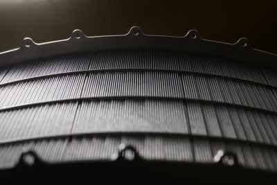
Intergalactic, an aerospace thermal management company, has pioneered a novel and innovative approach to heat exchangers that can significantly boost performance and effectiveness while minimizing impacts to weight and volume through its proprietary microtube heat exchanger technology. The technology brick that makes this feat possible is in the hundreds to tens of thousands of tiny tubes that do the heat transfer between fluids and can be seen in Figure 1 and Figure 2.
Figure 2. Microtube heat exchanger core looking into the tube side. First image shows a divider plate used for multi-passing on the shell side.
Intergalactic has designed and tested microtube heat exchangers for a number of different working fluid applications including refrigerants, air, and liquid coolants such as polyalphaolefin (PAO), propylene glycol (PGW), ethylene glycol (EGW), and ocean salt water. Working pressures for different tested microtube heat exchangers have ranged from as low as a few psi at high altitude ambient to as high as tens of thousands of psi in deep undersea applications. Working temperatures can go well below freezing to as high as hundreds of degrees Celsius depending on the application.

THE PHYSICS BEHIND MICROTUBES
The physics behind tube bundle heat exchangers have long been studied and are well known across many industries aside from aerospace. Heat exchanger capacity in general is often characterized by an overall UA, the overall heat transfer coefficient multiplied by the available heat transfer surface area, respectively. The heat exchanger UA is determined by all the thermal resistances between the two fluid medias exchanging heat, and commonly made up of three terms: the convective resistance between the hot fluid and the heat exchanger material, the conductive resistance of the heat exchanger material itself, and then the convective resistance between the cold fluid and the heat exchanger material.
Conduction resistance is often fairly negligible as heat exchanger materials typically have high thermal conductivity and the thickness is fairly small. The ratio of convective to conductive heat transfer at the fluid boundary is defined as the nondimensional Nusselt number, Nu = h·D/k, where h is the heat transfer coefficient, D is the characteristic length (the tube diameter in this case), and k is the fluid thermal conductivity. It is often characterized in the literature in the form of Nu = C·RemPrn for turbulent flow where C is a constant coefficient, Re is the nondimensional Reynolds number that characterizes inertial versus viscous forces in the fluid, Pr is the nondimensional Prandtl number that characterizes momentum diffusivity versus thermal diffusivity, and m and n are constants often derived empirically. For laminar internal flow in a tube, the Nusselt number is just a constant.
Assuming a fixed given core volume and fixed inlet boundary conditions for each fluid, it can be shown that the heat exchanger UA scales with diameter approximately by 1/D(2-m) to 1/D2 where m can range from 0.6 to 0.8 depending on whether flow is internal to the tube (e.g. the Dittus-Boelter equation) versus external over a tube bundle, in which case tube spacing also plays a role (Grimson ED. Trans ASME, 59, 583, 1937). The UA scaling to diameter is also a function of flow regime, whether it is laminar or turbulent and which convective resistance is dominant. With that in mind, heat exchanger UA generally scales between ~1/D1·2 to ~1/D2.
Conventional tube-shell heat exchangers typically have tube diameters in the neighborhood of 0.25 in. to 0.5 in. (~6 mm to ~13 mm). These diameters are on similar scales to conventional plate fin heat exchanger channel heights which typically range between 0.1 in to 0.5 in. Channel heights much smaller than that typically result in difficulty handling and stacking the fins and plates during the plate fin heat exchanger construction assembly. This limitation fundamentally restricts how much heat transfer surface area can be packed into a given fixed volume for these conventional heat exchanger technologies. At Intergalactic, we’ve designed and built microtube heat exchangers with tube diameters down to 0.02 in.
Assuming diameters on a conventional heat exchanger is limited to a minimum of 0.1 in., using the previously defined scaling, the microtube heat exchanger can theoretically offer an ~7x to potentially an ~25x increase in UA, which is directly proportional to the Number of Transfer Units (NTU) that often is used to determine heat exchanger effectiveness. What’s more, all the additional surface area for the microtube heat exchangers is all primary heat exchanger surface area, meaning that both fluids are in direct contact with the heat exchanger material, i.e. the tube walls.
Plate fin heat exchangers will try to augment heat transfer area by adding secondary heat transfer area in the form of additional fins. This secondary area is less effective than primary area because the fin is not perfectly efficient due to additional resistance encountered when first conducting heat from the fin to the primary surface area of the plates. This inefficiency results in a larger, heavier conventional heat exchanger compared to the microtube heat exchanger for the same performance.

MICROTUBE TECHNOLOGY IN PRACTICE
The increase in UA for microtubes translates to a heat exchanger with a much higher effectiveness than a conventional heat exchanger, and that delivers more performance for the same volume. In practice, Intergalactic routinely observes that microtube heat exchangers have shown 3x to 4x the capacity of a conventional plate fin heat exchanger for the same core volume. Alternatively, if one is more sensitive to weight or volume, one could shrink down the size of a microtube heat exchanger to maintain the same performance as a conventional heat exchanger, but significantly reduce weight and installation footprint. In real-world aerospace applications, Intergalactic has seen 50%-80% reduction in weight and/or volume for microtube heat exchangers compared to conventional heat exchanger technology.
Another benefit microtube heat exchangers have over conventional plate fin is the tubes are made of stainless steel or other high-performance alloys, making them stronger and more resistant to damage brought on by Foreign Object Debris (FOD) that would have manifested itself as bent aluminum fins and degraded performance. Stainless steel is also less likely to foul and/ or corrode in the field when exposed to harsh environments.
It should also be noted that conventional plate fin heat exchangers often employ brazing to join the fins and plates together. That process can be inconsistent, and the quality is highly dependent on the braze method. The brazing operation can also include a process step of removing oxides that are built up during the braze and may require subjecting the heat exchanger to “pickling solutions” that often contain acids to eat away the oxides. Intergalactic employs a proprietary laser welding process to join the microtubes to the heat exchanger end plates, resulting in a simpler and cleaner manufacturing process and a more mechanically robust product.
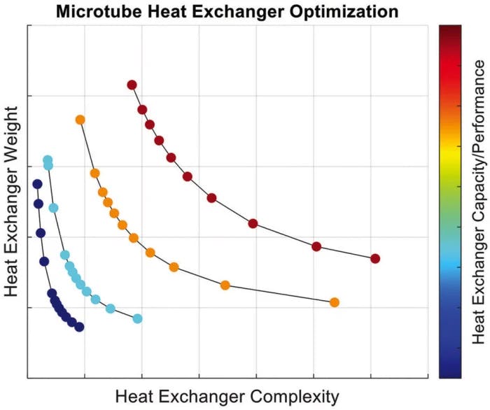
During preliminary design, trade studies between the factors such as performance, weight and volume, and heat exchanger complexity (which often translates to development and production costs) are often done in trying to find an optimal design. Intergalactic has developed in-house analysis methodology and analytical toolsets to quickly evaluate these types of trades by generating pareto fronts against different trade factors such as the ones discussed.
The optimization process will then size and optimize design parameters such as tube spacing, number of passes, tube diameter, wall thickness, etc. subject to a set of formalized constraints, fluid inlet boundary conditions, and an objective function. Pareto optimality is reached when a design cannot improve one of these design goals without making at least one of the other design goals worse, e.g. increasing performance but at the expense of increasing weight. The pareto front is made up of the menu of different pareto optimal solutions and is a great visualization tool to help the analyst select the heat exchanger design that best suits the objectives of a specific customer and platform.

Figure 3. Optimization analysis artifact showing pareto fronts for different optimal heat exchanger designs.
By formalizing the constraints and objective function and automating the optimization process, a hundred different optimal possible design options can be assessed within minutes where in the past only a handful of design evaluations previously could be evaluated because of time or resource constraints. This is one of the major benefits we’ve observed by adopting a Model Based Design approach to system design and analysis. An example of this analysis artifact is shown in Figure 3 where several different pareto fronts are shown for different levels of heat exchanger capacity/performance with a common set of hot side and cold side boundary conditions and pressure drop constraints, a typical requirement in heat exchanger design.
These performance models, along with the solid model, form the backbone of the heat exchanger Digital Twin. This is further informed and matured through testing of first a small-scale sample representative of the core geometry in Intergalactic’s dedicated wind tunnel testing chamber and then eventually the full-scale heat exchanger on the integrated test bench that often is only one component of the final thermal management system.
This article was written by Tony Ho, PhD, Director of Systems Engineering, Intergalactic (St. George, UT). For more information, visit here .
(Note: This article originally was published in Aerospace & Defense Technology's Tech Briefs. Read the article here: https://www.aerodefensetech.com/component/content/article/adt/features/articles/40853)