We tested an aerospace environmental control system (ECS) for 100 hours and took copious notes for you
Blog
When you’re qualifying hardware for next-generation aerospace programs, you have to shake, bake, and generally beat the tar out of your working prototypes to make sure they’re tough enough for prime time. If you’ve ever wanted a complete tear-down of that testing process, you’re in the right place.
At Intergalactic, we have a growing menu of commercial off-the-shelf aerospace products and new innovations in thermal management technology. Anytime you introduce a new product or system to the aerospace industry, it has to go through rigorous testing to achieve “qualification.” For this project, we spent 100 continuous hours testing every aspect of an environmental control system that will be used on a franchise defense program.
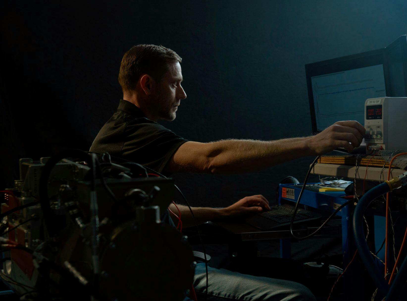
Our amazing Test Engineer, Josh Fawson, has been leading this testing and qualification effort at Intergalactic. This post includes his field notes, observations, and real test data.
Why did we test our aerospace ECS for 100 hours?
The purpose of this 100-hour test was to get more extensive, continuous runtime on an environmental control system (ECS) we’ve been developing for years with a Tier One defense customer at nominal operating temperatures.
We do testing all the time, so this effort wasn’t the first time we’d put this thermal management system through its paces. During bench testing and integration, we accumulated hundreds of hours of runtime and data, but that was intermittent across several different units and configurations as we refined our product and honed-in on the optimal design.
What were the testing conditions for this aerospace ECS?
We conducted testing in Q3 of 2021 at Intergalactic Headquarters in St. George, Utah. Testing was conducted indoors in a climate-controlled environment, which allowed the use of a radiator / fan assembly with conditioned ambient air for platform cooling instead of a vapor cycle chiller. It also provided a modicum of comfort to the engineers conducting the test. (We don’t want our engineers to melt and die!)
How did we set up the testing process?
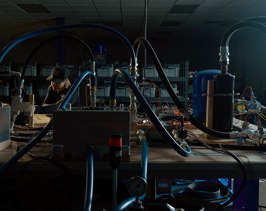
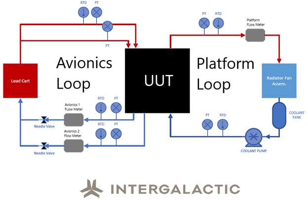
We used external equipment to mimic the avionics heat load and platform heat sink. We deployed two immersion heaters to add heat to the avionics coolant, and we used a radiator / fan assembly to remove heat from the platform coolant. We also leveraged external sensors and meters to verify proper system functionality and validate internal sensor accuracy.
What were the electrical requirements for testing the ECS?
All our systems, components, and equipment are native high voltage DC. We deployed electrical requirements at multiple phases to satisfy the requirements for system testing.
- 480 VAC, 3 Phase
- 208 VAC, 3 Phase
- 240 VAC, 1 Phase
- 120 VAC, 1 Phase
What was the testing schedule?
Testing began on a very warm summer night in Southern Utah at 8 p.m. local time. Intergalactic’s testing team included engineers Josh Fawson, TK Bush, Joe Renaud, and Andy Kerlin. The engineers all took shifts until testing was completed at midnight five nights after testing began. Data was continuously recorded throughout the entire testing envelope with new data files being created every hour.
What were the testing procedures?
Small details matter when testing precise aerospace system hardware and software. Our crack team followed all the procedures below for testing:
- Verify that all power cords are plugged into the appropriate outlets.
- Connect all external hoses and electrical cables to their couplers on the test unit (UUT).
- Start the platform pump.
- Check platform flowrate using system graphic user interface (GUI).
- From the GUI, verify that internal and external pressures and temperatures are within system operating parameters.
- Power on the test unit (UUT)
- Use GUI to begin logging data into a CSV file.
- Turn on immersion heaters and adjust power input to match the [TH1] input requirement.
- Turn on radiator fans and adjust automated temperature control to nominal heat sink temperature.
- Continue to monitor system and external sensors for any anomalies.
- Every hour, start new CSV file to log data.
- Every hour, record current draw from 270 VDC power supply, ambient temperature, ambient pressure, nominal compressor speed, power input to the immersion heaters, and initial refrigerant charge.
- Check power output of the immersion heaters and adjust to match the input requirement.[TH2]
- Upon conclusion of 100-hour continuous test, turn off immersion heaters, close final data file, stop radiator fans, turn off power to test unit (UUT), and turn off platform pump.
What data did the tests produce?
Our nearly weeklong testing adventure produced some incredible data. Take a look.
Below is a diagram of our testing setup.
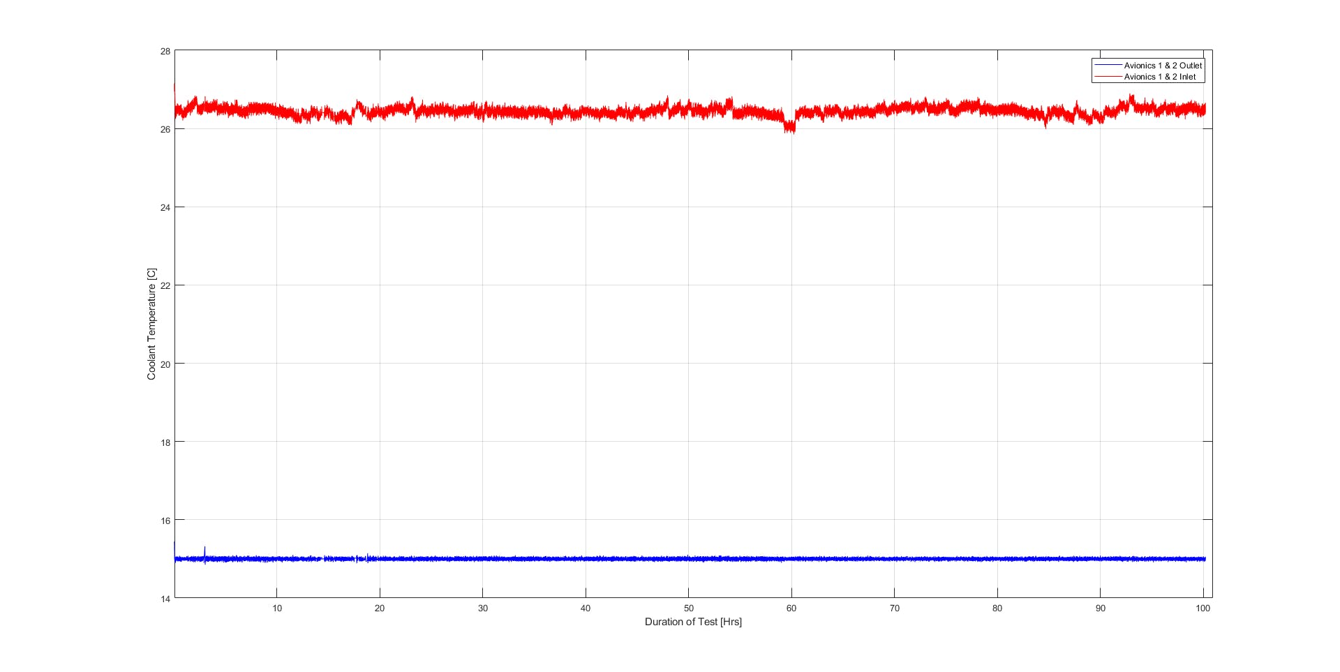
The figure below illustrates our Avionics coolant data. Note that we excluded any outlying data from Max and Min that resulted from startup or technician errors.
Avionics 1 & 2 coolant inlet data:
- Average coolant temperature: 26.44°C
- Maximum coolant temperature: 26.89°C
- Minimum coolant temperature: 25.85°C
Avionics 1 & 2 coolant outlet data:
- Average coolant temperature: 15.00°C
- Maximum coolant temperature: 15.11°C
- Minimum coolant temperature: 14.89°C
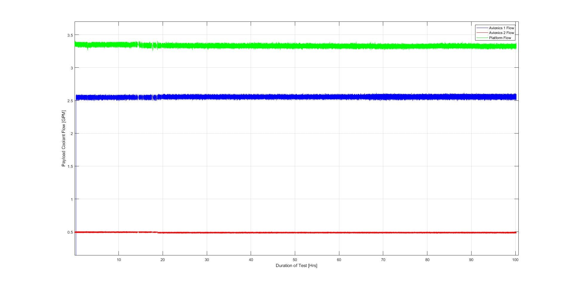
Below is our coolant flow data, minus outliers from startup or technician error.
Avionics 1 coolant data:
- Average coolant flow: 2.55 GPM
- Maximum coolant flow: 2.62 GPM
- Minimum coolant flow: 2.49 GPM
Avionics 2 coolant data:
- Average coolant flow: 0.49 GPM
- Maximum coolant flow: 0.51GPM
- Minimum coolant flow: 0.47 GPM
Platform coolant flow data:
- Average coolant flow: 3.33 GPM
- Maximum coolant flow: 3.41 GPM
- Minimum coolant flow: 3.25 GPM
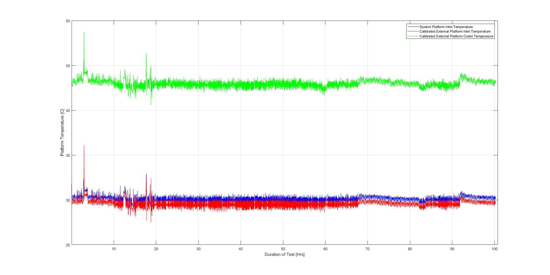
Below is our platform coolant data, minus outliers from startup or technician error.
Platform coolant out data:
- Average coolant temperature: 42.97°C
- Maximum coolant temperature: 44.18°C
- Minimum coolant temperature: 41.38°C
Platform coolant in data:
- Average coolant temperature: 30.11°C
- Maximum coolant temperature: 30.98°C
- Minimum coolant temperature: 28.84°C
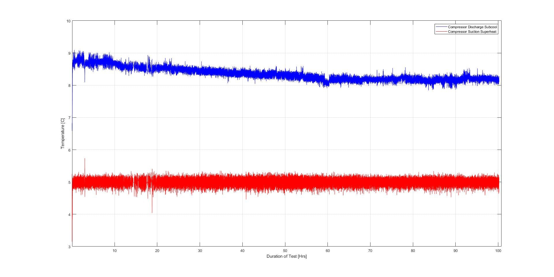
Below is our refrigerant superheat and subcool data, minus outliers from startup or technician error.
Superheat data:
- Average superheat: 5.00°C
- Maximum superheat temperature: 5.41°C
- Minimum superheat temperature: 4.46°C
Subcool data:
- Average subcool: 8.34°C
- Maximum subcool: 9.09°C
- Minimum subcool: 7.84°C
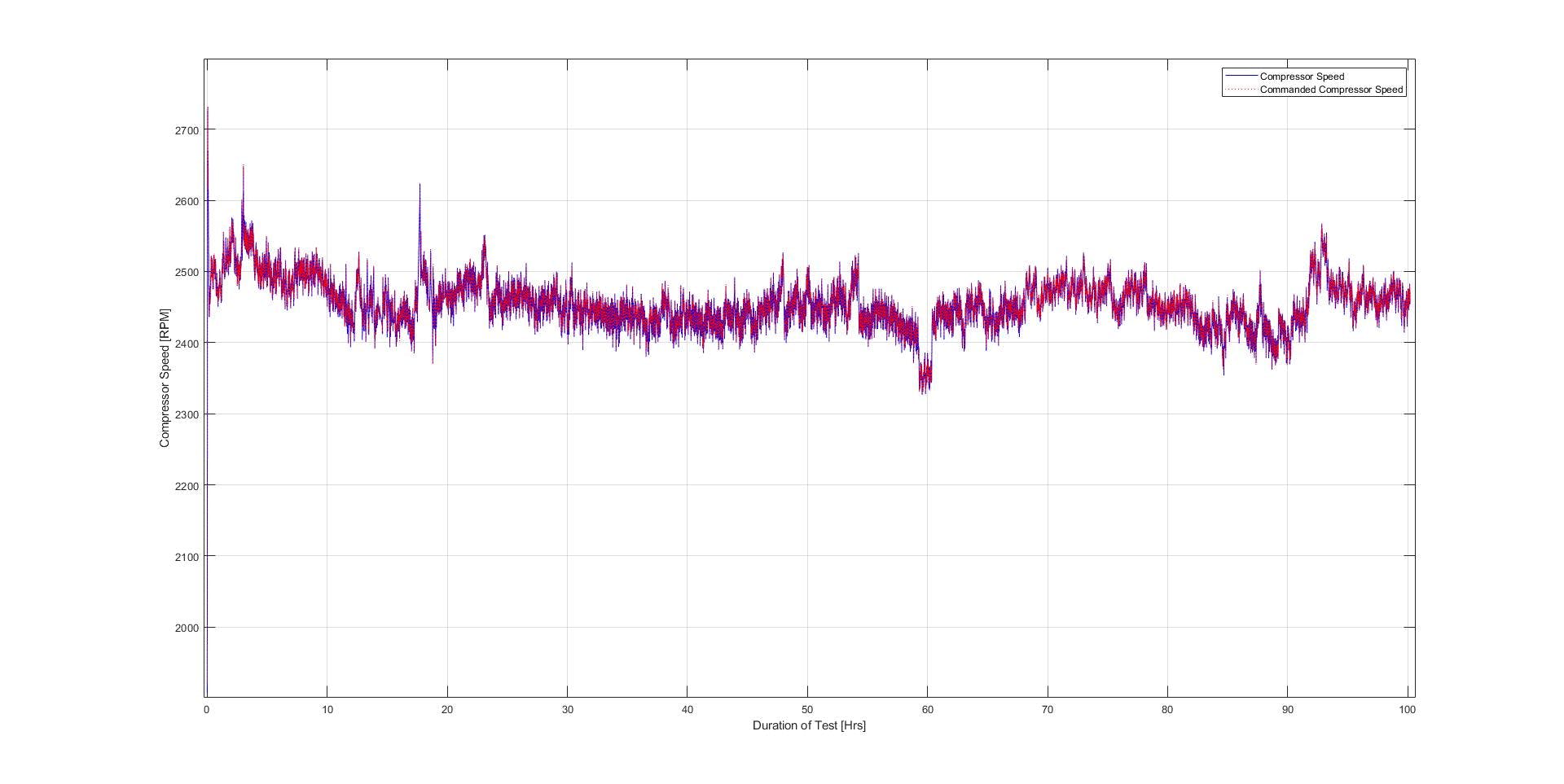
Below is our compressor speed data, minus outliers from startup or technician error.
Compressor speed data:
- Average compressor speed: 2455.0 RPM
- Maximum compressor speed: 2731 RPM
- Minimum compressor speed: 2326.6 RPM
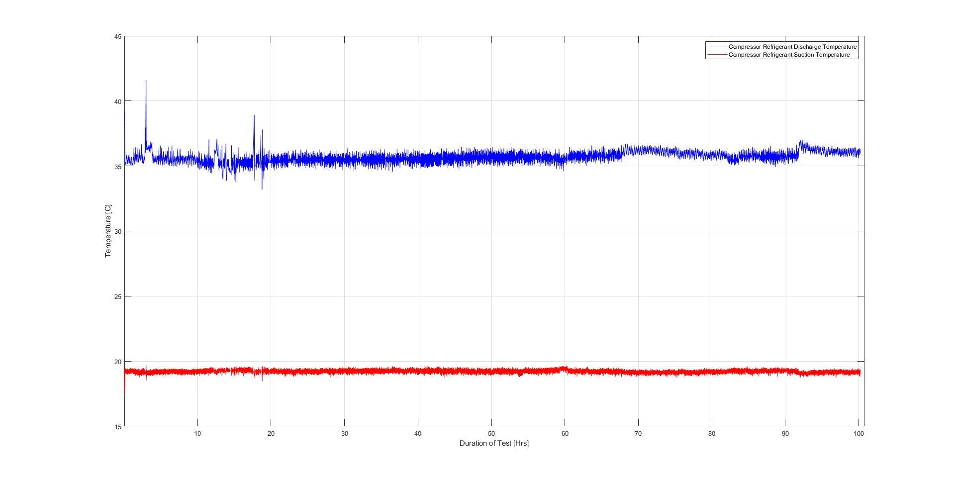
Below is our compressor discharge and suction temperature data, minus outliers from startup or technician error.
Discharge data:
- Average discharge temperature: 35.48°C
- Maximum discharge temperature: 36.98°C
- Minimum discharge temperature: 33.96°C
Suction data:
- Average suction temperature: 19.22°C
- Maximum suction temperature: 19.69°C
- Minimum suction temperature: 18.45°C
Below is our compressor discharge pressure data, minus outliers from startup or technician error.
Discharge data:
- Average discharge pressure: 164.10 PSIA
- Maximum discharge pressure: 169.67 PSIA
- Minimum discharge pressure: 156.89 PSIA
Suction data:
- Average suction pressure: 69.10 PSIA
- Maximum suction pressure: 72.88 PSIA
- Minimum suction pressure: 68.17 PSIA

After the tests, we ran a full system check
After the testing was completed, we inspected key components for visible wear. We examined the coolant pump for wear on the moving parts and inspected the condensing heat exchanger for burn-in foreign object debris (FOD) from the compressor. All parts revealed little to no signs of FOD, wear, or fatigue compared with their condition prior to the 100-hour test.
So, did the ECS pass the test?
The 100-hour test was successful and our aerospace ECS performed beautifully. The system never shut down or stopped providing avionics coolant at the required temperature and tolerance. All components performed to specification for the entire duration of the testing period and showed minimal to no signs of wear at the conclusion of testing.
Reach out to your friendly neighborhood thermal experts
If thermal management is a challenge on your aerospace program, we’re ready and able to assist. We do clean-sheet environmental control system and component designs, and we have a bunch of great off-the-shelf aerospace thermal management solutions. You can reach us anytime at phonehome@ig.space.
- Josh Fawson, Intergalactic Test Engineer