Vapor cycle thermal management systems: an overview
Blog
If you’ve ever grabbed an ice-cold beverage from your kitchen fridge on a hot summer day, or relaxed in your Chevy Tahoe’s pleasantly cool, 71-degree interior while looking out the window at a blisteringly hot Death Valley in late July, you’ve experienced the almost magical benefits of a vapor-cycle thermal management system. Widely used in aerospace, automotive, industrial, and residential cooling and heating, vapor cycle systems vary in size, power, and complexity, but they all rely on some basic principles and components to function. Let’s go over some of the basics of this fascinating (and very cool) technology.
How does a vapor cycle system work?
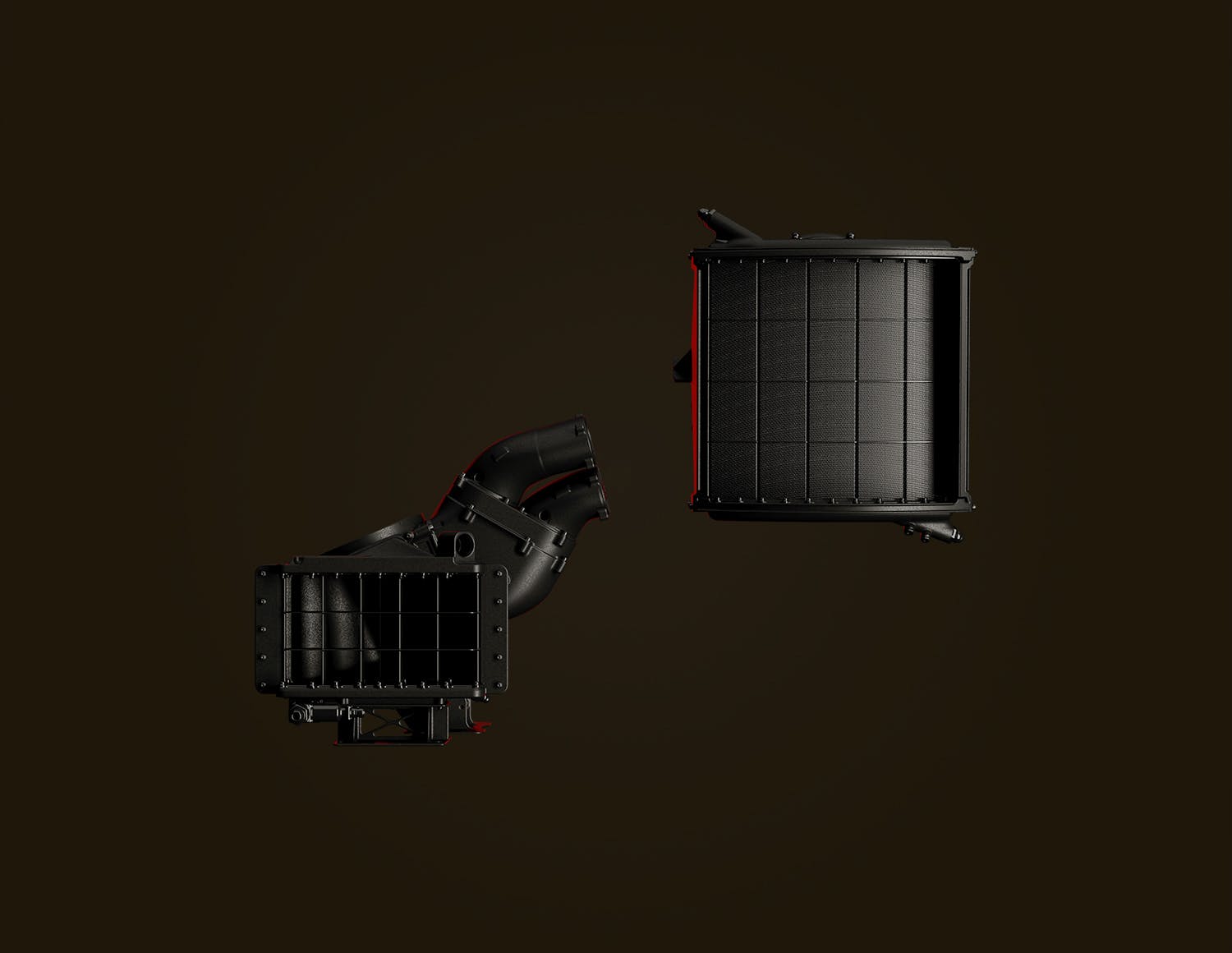
There are multiple designs for vapor cycle thermal management systems, from the quite simple to the very complex. However, nearly all vapor cycle systems follow the same basic design, and utilize the same 5 basic components (more complex systems may utilize added loops, water chillers, and/or heat exchangers, but nearly all will follow the general structure below). Let’s start with the compressor.
Compressor
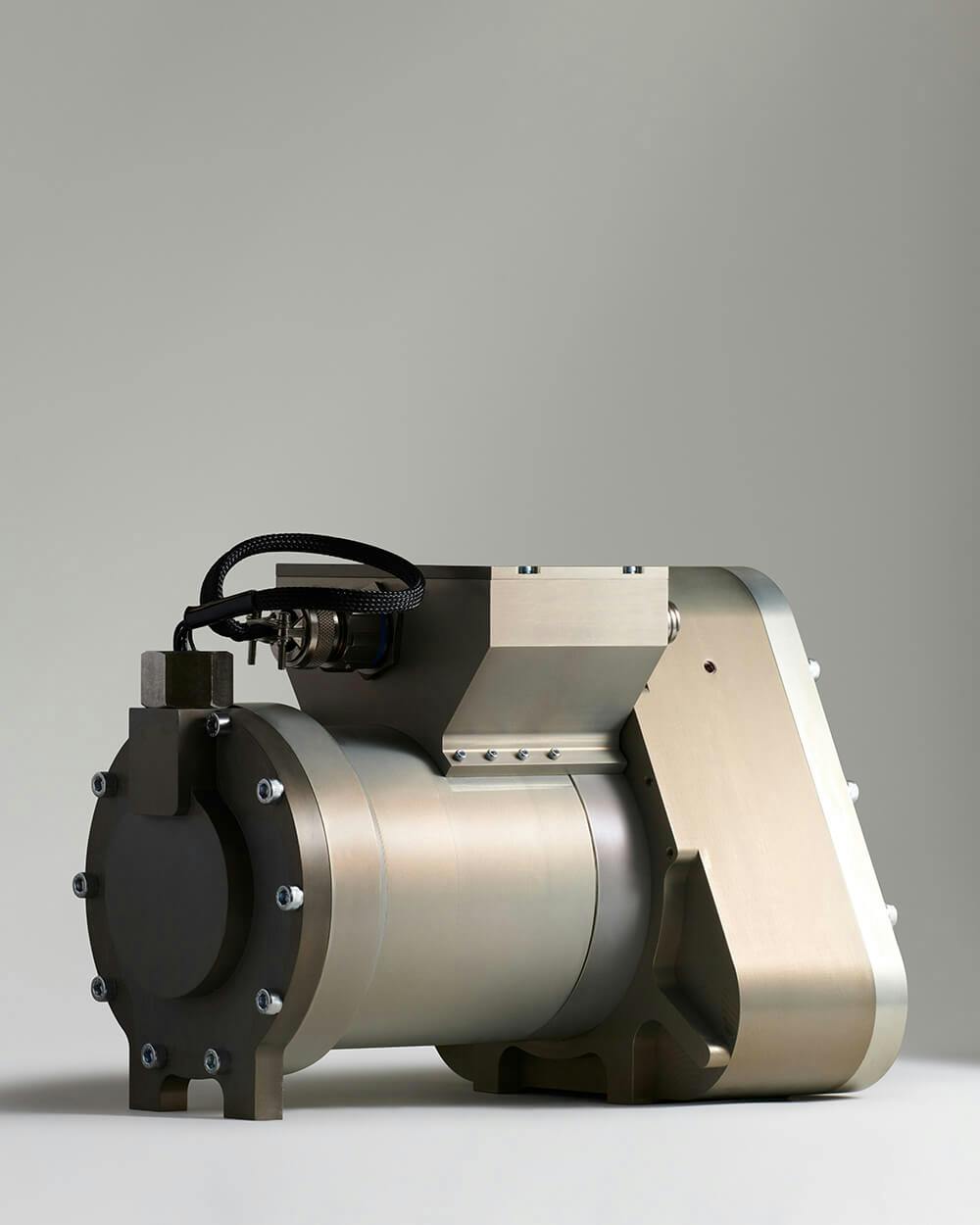
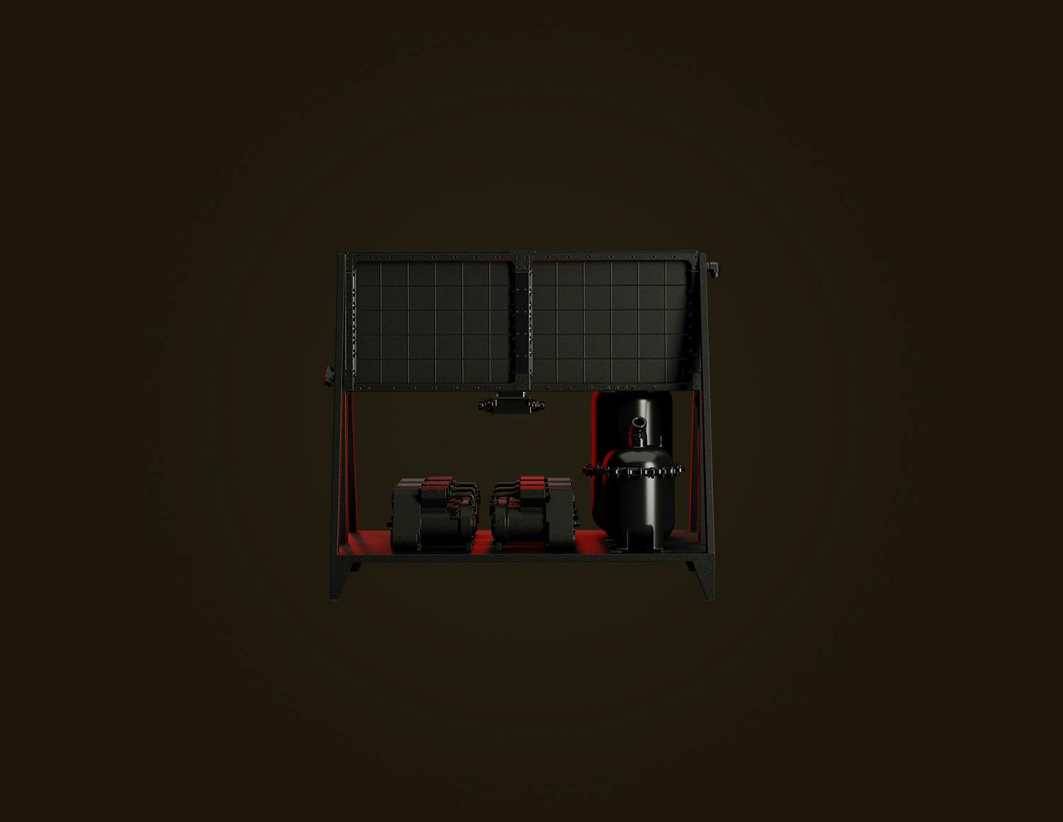
Since vapor cycle systems function on the principle of heat transfer when pressurized fluids change from liquid to gas and back, the system must necessarily be pressurized. This requires some type of compressor. In a vapor-cycle thermal management system, low-pressure refrigerant gas enters the compressor and is raised in both pressure and temperature as it is compressed. In very early air-conditioning systems, the compressor could be driven by steam, wind, or even horsepower (using actual horses), but the majority of compressors in today’s vapor cycle systems are electrical (like the one in your home refrigerator), or are driven off belts and pulleys from an internal combustion engine (say, in your car).
Compressors commonly take one of three main forms, though there are others:
- Reciprocating or piston-type compressor: This compressor in its most basic form includes a cylinder, two chambers for suction/intake and discharge, at least one piston, an orifice, and a one-way reed that covers that orifice. In simple terms, this type of compressor functions very similarly to a single-cylinder internal combustion engine, but without the intake of fuel and expulsion of exhaust gases. The piston moves in a reciprocating manner to compress the gas. More robust reciprocating compressors may have two pistons moving in opposite directions to help balance out the system, reduce vibration, and improve efficiency.
- Scroll or spiral-type compressor: This compressor commonly features two interconnected snail-like spiral structures rotating within an outer housing, and mounted on a central shaft. As the scrolls spin and the space between the interleaved walls or vanes reduces, the fluid within the walls is compressed.
- Rotary compressor: Rotary compressors may be of the lobe-type, screw-type, vane-type, or liquid ring type, but each has an outer casing containing one or more rotating elements. In concept the basic liquid-ring rotary compressor is similar to the axial fan or turbocharger (which moves air), with a main rotor spinning on its axis within an outer housing (which is elliptical in the case of the liquid-ring compressor). However, in a rotary compressor there is no space between the vanes of the rotor, as it resembles a solid disk with raised blades. The liquid intake and outlet ports are near the center of the rotating disk. One advantage of this type of compressor is that it needs no valves or reeds/orifices to direct the liquid or gas, and has very low vibration when running.
Condenser
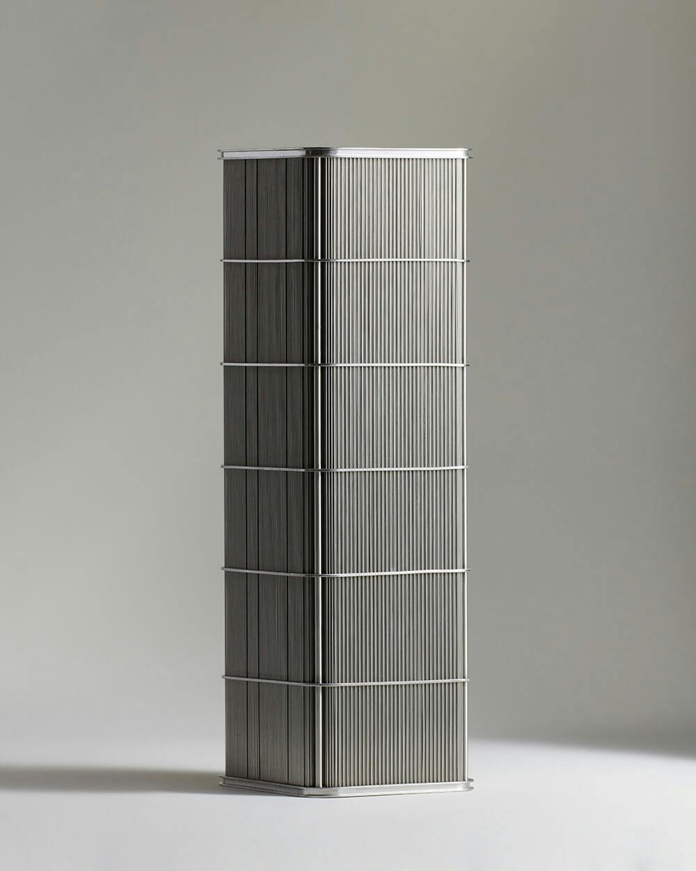
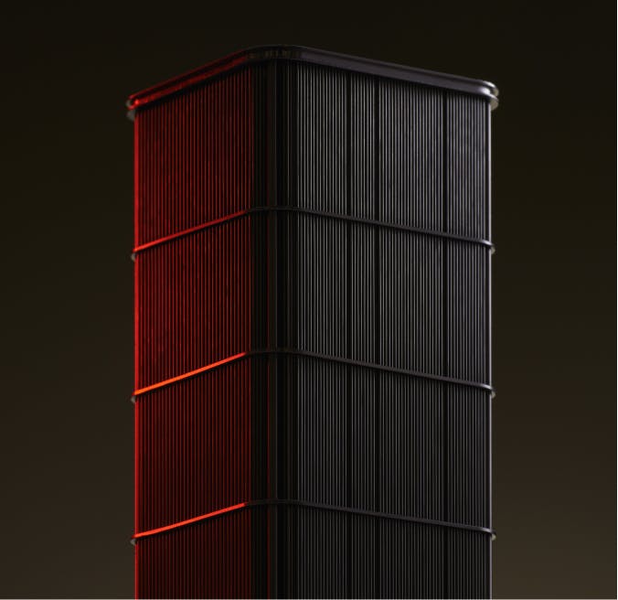
The high-pressure, high-temperature vapor exits the compressor and enters the condenser, which is one of two heat exchangers utilized in most vapor-cycle cooling systems. The condenser is essentially similar to the radiator in your car, with a series of loops of piping/tubing interconnected by radiating fins. The relatively cool ambient air (on earth-bound systems, anyway) passes over these fins and cools the refrigerant vapor, which condenses into a liquid before moving along the system.
Expansion valve
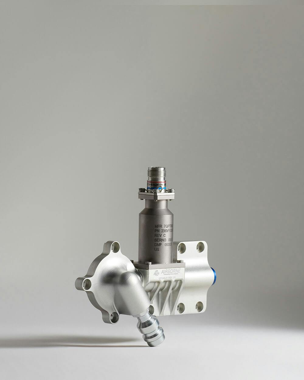
After leaving the condenser, the liquid refrigerant often enters a receiver-dryer, which acts as a reservoir and may filter the refrigerant and/or remove water from the system. However in very simple vapor cycle systems, the liquid refrigerant may directly enter the expansion valve. Expansion valves come in various configurations, including the fixed-orifice type (the simplest), thermostatic or thermal expansion valves, and electronic expansion valves.
The expansion valve (sometimes just called the valve or the expansion device) sets the stage for the full transition of liquid refrigerant back into a gas by spraying a measured amount of pressurized, liquid refrigerant through an orifice into an expansion chamber, dramatically lowering the pressure and temperature of the refrigerant. This rapid drop in pressure causes some of the liquid to boil. This is called flashing. This vaporized liquid mixture is still not fully a gas, but rather a two-phase combination of fine liquid droplets and gaseous refrigerant that optimizes the efficiency of the next step in the process.
Evaporator
This is the final step in the loop, and is where the payoff is made for all the work so far. The evaporator is the second heat exchanger in the system, and its function is to absorb heat from the air. As the low-pressure refrigerant enters the evaporator, relatively hot ambient air is blown (typically using an axial fan) across the radiating fins and tubes of the evaporator, transferring its heat into the refrigerant, which completes its phase-change from liquid droplets back into a gas. The resulting cool air is distributed via vents or ducting wherever you want cool air to go, such as an aircraft’s cabin or avionics system, the inside of your home refrigerator/freezer, an interior room of a building, or the passenger compartment of an automobile, train, or ship.
From the evaporator, the gaseous refrigerant enters the compressor, and the circle of life, er… the vapor cycle repeats as long as the system is operating.
Refrigerant
We said above that the vapor-cycle thermal management system typically has 5 components, and we consider the refrigerant one of these key items. After all, a vapor-cycle system depends on a liquid refrigerant capable of changing phases within a certain window of pressures and temperatures. Modern refrigerants are man-made chemicals, and have become a blessing and a curse for humankind, as we’ll see later.
Advantages of vapor cycle thermal management systems
There are multiple advantages of using vapor cycle systems, particularly for aerospace and automotive applications. Let’s go over a few of the biggies.
Compactness and lightness
Any time space is concerned, space is a concern. What we mean by this is that all systems in spacecraft and aerospace vehicles are constantly under rigorous scrutiny to ensure they are as compact and light as possible. If you can save grams of weight or cubic centimeters of space, it’s often worth the extra effort and expense. Vapor cycle systems can be made in extremely compact packages, particularly those using today’s advanced, microtube heat exchangers designed specifically for aerospace applications.
Flexible cooling and/or heating (can be used for both)
Depending on how they are set up, vapor cycle thermal management systems primarily meant for cooling may also be used for heating through the use of reversible heat pumps, which enable the refrigeration cycle to be reversed and provide heating instead of cooling. When the heat pump is in heating mode, the evaporator coil simply switches roles and becomes the condenser coil, producing hot air, while the condenser unit acts as the evaporator, discharging cold air to the exterior space. Depending on climatic conditions, this setup can meet both heating and cooling needs, with the additional advantage that heat pumps are typically much more energy efficient than electric element-type space heaters or fossil fuel-based boilers used for this purpose.
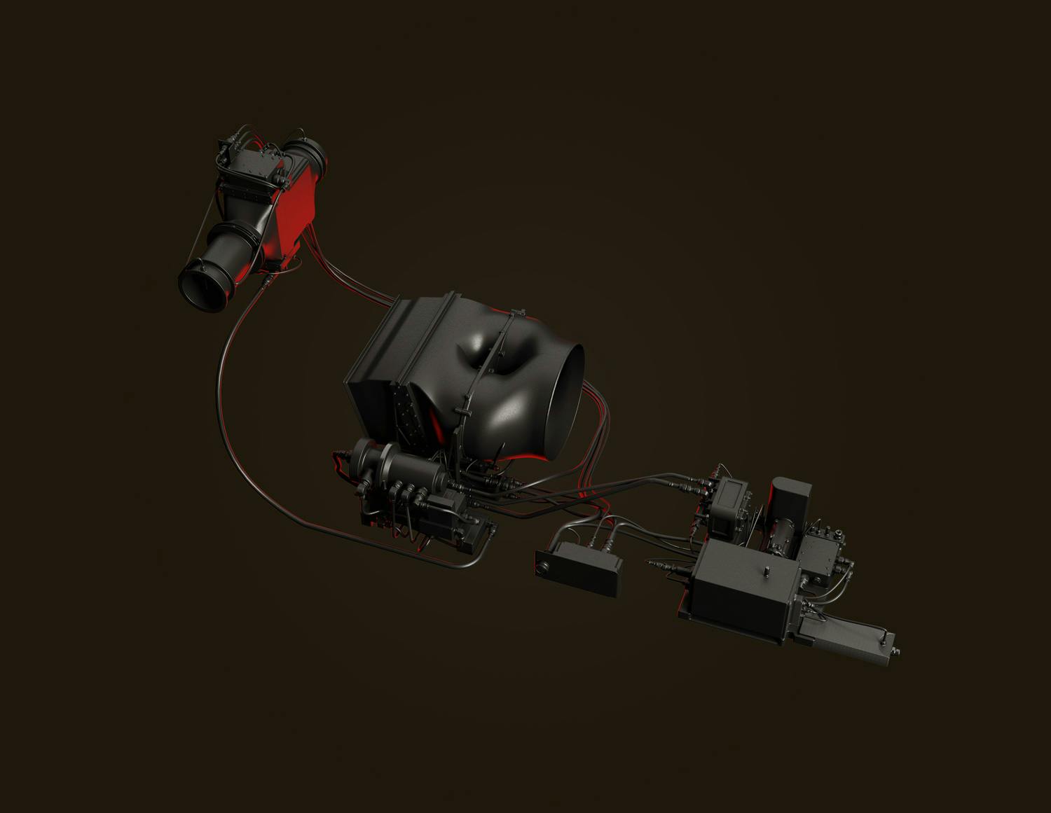
In a spacecraft or eVTOL where weight and space are extreme priorities, an ECS (environmental control system) that can both cool and heat the cabin is a huge benefit.
Reliability
With well over a century of refinement and enhancements behind it, the vapor cycle system has gotten very reliable. It’s not uncommon to find automobile air-conditioning systems functioning just as well today as they did when the car was parked in 1960, using the original refrigerant charge. You used to be able to count on your refrigerator running for literally decades with minimal or no maintenance. This extreme longevity has been tempered somewhat by various marketspace factors, planned obsolescence, and environmental issues—more on this below—but vapor cycle systems in general are still quite reliable.
Disadvantages of vapor cycle cooling systems
When it comes to the effective transfer of heat in a relatively small and light package, the vapor cycle system is almost all upsides. However there are some cons to this setup, and some are becoming significant issues.
Air conditioning consumes a large percentage of the world’s electrical power, and efficiency varies
Electrically powered, vapor-cycle, residential air conditioning is contributing to a transition of global population toward hotter areas of the globe, where demand for A/C of course increases still further. There are now about 1.6 billion A/C units in use, with over half in China and the United States. However, the lion’s share of the projected growth in energy use for space cooling by 2050 comes from the emerging economies, with just three countries—India, China and Indonesia—contributing half of global cooling energy demand growth.
All of those A/Cs vary enormously in energy efficiency, and keeping them running consumes over 2,000 terawatt hours (TWh) of electricity every year—two and a half times the total electricity use of the continent of Africa. Almost a fifth of all electricity used in buildings globally is used for cooling, and in some countries in the Middle East and also parts of the United States, keeping buildings and homes cool can consume more than 70% of available peak residential electricity on extremely hot days. You may already have experienced “rolling blackouts” or brownouts if you live in California or the New York area in hotter weather.
The world’s governments are attempting to implement stricter regulations for efficiency of air conditioners, in order to avoid a global “cold crunch” where the demand for A/C greatly outstrips available power supplies.
Vapor cycle coolant/refrigerant is often harmful to the environment and ozone layer
While a properly functioning, properly maintained vapor cycle system is generally efficient, reliable, and “clean,” things are not always hunky-dory. Historically, refrigerants have been corrosive or toxic (like chloromethane, ammonia, and sulfur dioxide), and leaks and system failures can occur, especially where vapor cycle systems aren’t properly maintained.
Around the 1930s, chlorofluorocarbons (CFCs) became the standard for non-flammable refrigerating fluids, dramatically improving the safety of air conditioners, but doing a serious injustice to the Earth’s ozone layer. Dichlorodifluoromethane (known as the DuPont trademark name Freon, Freon-12, or R-12) was safe and effective for cooling and was widely used in aerosol cans, but it was determined that CFCs harm to the ozone layer could result in potentially catastrophic environmental repercussions. International treaties have essentially banned R-12 except as a fire retardant in aircraft and submarines.
The problem is, people and airplanes and cars and buildings still get hot. Air conditioning is awesome. We’re addicted to it. Everybody wants some. So next, we tried hydrochlorofluorocarbons, commonly known as HCFCs, a group of man-made compounds containing hydrogen, chlorine, fluorine, and carbon. Like CFCs, HCFCs are (or were) widely used in aerosol propellants, industrial manufacturing, and vapor-cycle systems. Unlike the CFCs, however, most HCFCs are broken down in the lowest part of the atmosphere and pose a much smaller risk to the ozone layer.
But like the man says, there’s no such thing as a free lunch. HCFCs might be nicer to the ozone layer, but *bwah-bwaaaah* they are very potent greenhouse gases. Bummer. So, the use of HCFCs is also being phased out in favor of the kinder, gentler hydrofluorocarbons (HFCs).
As you can imagine, it’s difficult for vapor-cycle A/C techs in the auto, residential, industrial, and aerospace markets to keep pace with the continually changing requirements, permissible refrigerants, and conflicting/incompatible system designs. When one refrigerant is banned and another becomes “allowed” or is named as “the replacement” for a long-established chemical, often that replacement is also eventually banned, sometimes within only a few years.
Case in point: R-22 was supposed to replace R-12, but has also been banned. R-410A is an HFC refrigerant that was intended as a replacement or an upgrade to legacy Freon systems, but due to environmental concerns, US-built refrigerators using R-410A refrigerant have been banned as of January 1, 2021. HC-600a is currently the leading replacement refrigerant for new U- built refrigerators, but HC-600a is a blend of 50% isobutane (highly flammable) and 50% HFC-134a (non-flammable). So in an effort to be buddy-buddy with mother Earth, we have had to move backward toward flammable refrigerants again. In a spacecraft, burny-splodey stuff is generally not desirable outside the propulsion system.
Hopefully, some smart person is able to come up with a vapor-cycle refrigerant compound that is sufficiently effective, inexpensive, and environmentally friendly… otherwise we may soon find ourselves building 19th-century ice houses in our backyards.
–By Jeff Davis, Intergalactic Scribe
Sources:
https://www.sciencedirect.com/topics/engineering/scroll-compressors
https://www.sciencedirect.com/topics/engineering/rotary-compressors
https://www.superradiatorcoils.com/blog/4-main-refrigeration-cycle-components