Heat pipes and vapor chambers: how do they work and what’s the difference?

Blog
Engineers are clever folks. Ever since the invention of the steam engine, people have had to figure out innovative ways to deal with excess heat from machines and vehicles. While some heat (obviously) is required to make steam to drive the piston and perform work, too much heat can cause excess pressure, destroy components, and even injure or kill the operator. In today’s increasingly electric-vehicle world, well-publicized EV fires show that heat remains a problem in modern transportation and electronic systems, even in the absence of fossil fuels. (Incidentally, statistically EVs catch fire far less often than traditional internal-combustion-engined vehicles.)
In aviation and aerospace, the problem of heat has engendered multiple solutions ranging from the very complex to the very simple. Aerospace-specific microtube heat exchangers, vapor cycle systems, aviation air cycle systems, phase-change thermal capacitors, forced air cooling, cold plates, and heat sinks are all employed to shed heat from places where we don’t want it and/or keep heat in places where we do. Today we’re going to go over the basics of heat pipes and vapor chambers, which are very clever, non-powered, two-phase heat-shedding devices that fall somewhere on the lower end of the complexity spectrum, but which still have some nifty tricks up their technological sleeves.
What is a heat pipe and how does it work?
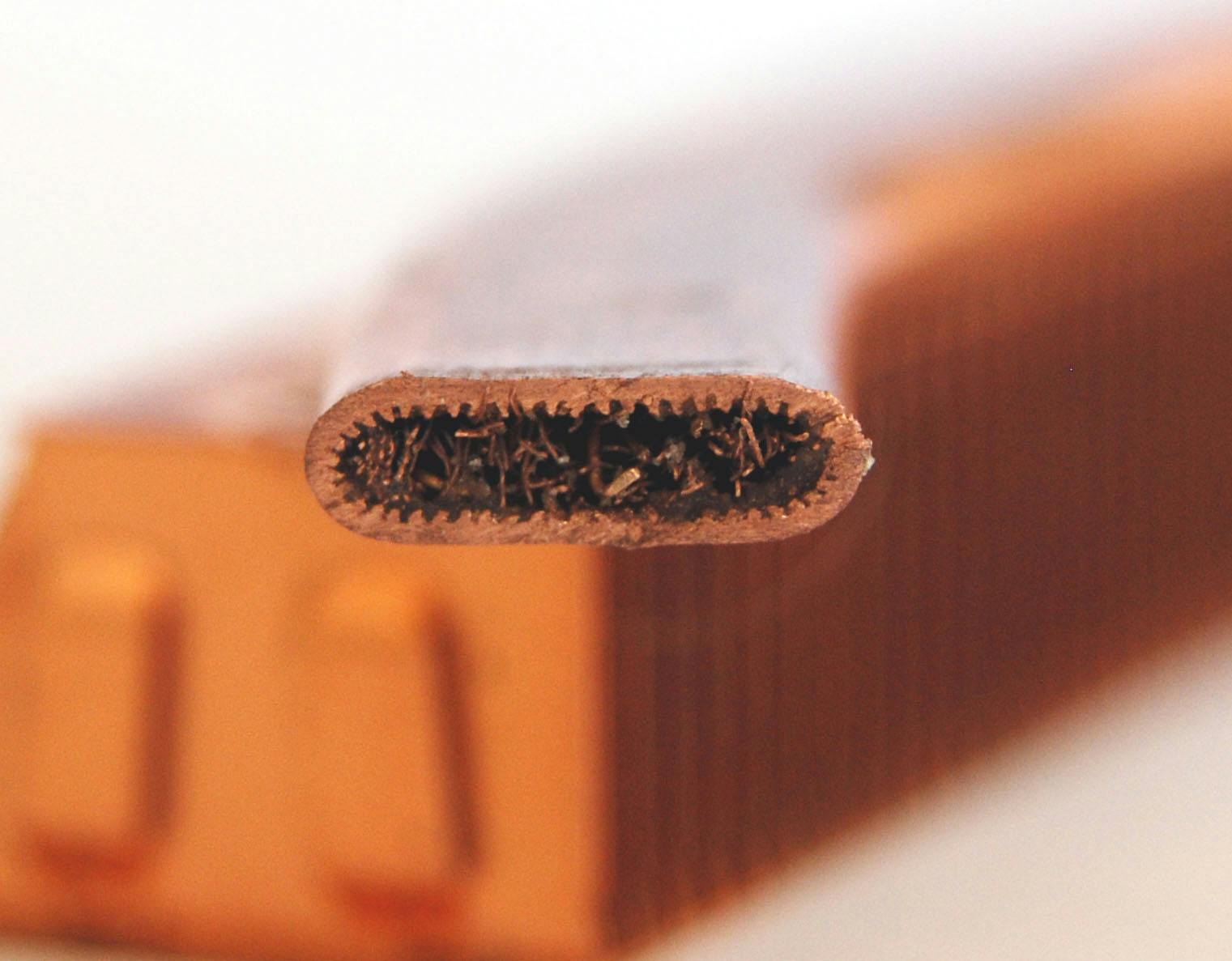
A heat pipe is a simple phase-change thermal management device generally resembling a hollow tube, typically round or oval in cross-section, with vacuum inside. Often made of copper, a heat pipe has high thermal conductance and is capable of moving a relatively large amount of heat linearly along the length of the tube, as long as there is a comparatively small difference between the “hot” and “cold” ends of the heat pipe.
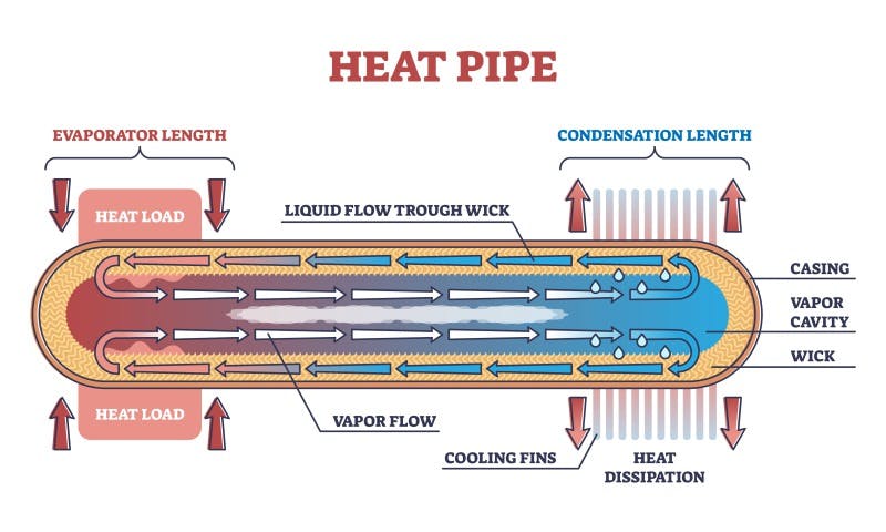
The metal tube is lined along its inside edges with what is known as a wick, constructed either of a metal mesh/screen material or sintered/compressed metal powder (often copper). In the center of the tube is an open space or vacuum cavity into which liquid vapor can move when a heat load is applied and evaporates the liquid (commonly deionized water, but other liquids are sometimes used).
As heat is applied to one end of the heat pipe, technically called the evaporator side, the liquid heats up and evaporates out of the mesh or powdered lining/wick and into the vacuum space of the vapor cavity. This creates a change in pressure (as heat increases, pressure increases) which helps move the liquid vapor down the center of the tube along the length of the heat pipe, shedding heat as it reaches the cooler, or condensation side. The condensation portion of the heat pipe may or may not be fitted with cooling fins to assist in heat dissipation, and it may or may not be connected to a heat sink. As the vapor sheds heat, it condenses back into a liquid and soaks into the wick. The liquid coolant is drawn through the wick back toward the evaporator portion via capillary action, and the cycle repeats.
Capillary action is when liquid flows through narrow spaces without external forces (like gravity), being aided by intermolecular forces (such as adhesion, cohesion, and surface tension) between the liquid and solid surfaces. (It’s also fundamental in distributing water throughout trees and other plants.)

Image courtesy DNP Group.
What is a vapor chamber and how does it work?
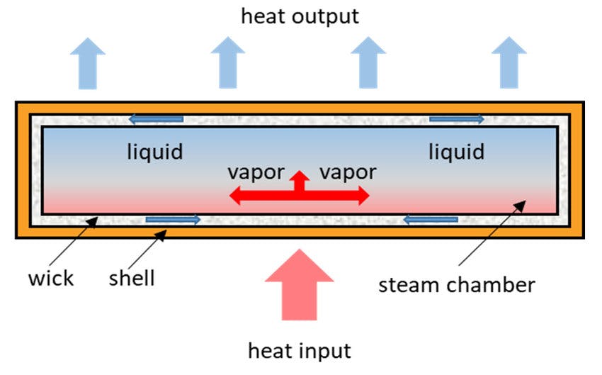
Vapor chambers are constructed of similar materials and use similar principles to spread heat, but function in a planar, or two-dimensional fashion, rather than linear. It can be helpful to think of a vapor chamber as a very flat, thin, wide heat pipe, where the top and bottom sides are parallel and the two pieces are joined only along the edges. In this case the evaporative area is the bottom of the vapor chamber, and the condensing/radiating area is the top. You place the vapor chamber with the evaporating surface directly on a heat source or sometimes adhere it using thermal materials, and it helps spread and dissipate heat from the system.
There are different ways to construct heat pipes and vapor chambers using different wicking materials and liquids, but generally a powdered/sintered copper wick layer and deionized water are used. The outer housing of a vapor chamber is typically constructed of copper, aluminum, stainless steel, or titanium. Because the top and bottom panels are so close together, the vapor chamber typically has internal supports to keep the panels from collapsing. A vapor chamber can be made very thin, down to around 2.5 mm (~0.01”) in general usage, though some brainy folks have developed vapor chambers just 200 microns (0.00787”) thick, or about twice as thick as the average human hair. Vapor chambers are generally rectangular or square in shape (though custom-shaped ones abound), and sizes of vapor chambers range from 25 x 25 mm (~1 x 1 inches) up through various square and rectangular sizes up to a maximum of around 250 x 250 mm (~10 x 10 inches).
Vapor chambers are often used in LEDs, graphics cards, laptops, mobile devices, servers, avionics, hard drives, and similar items.

Image courtesy Researchgate.
When would you choose a heat pipe vs. a vapor chamber?
The situations aren’t set in stone, and different users may select one over the other in similar circumstances. However, generally speaking, heat pipes are used to move or transfer heat to a remote heat sink or other thermal management device, usually for distances greater than about 50 mm (~2 inches), while vapor chambers are attached directly to a heat source and are used to spread heat in multiple directions (but generally up/outward relative to the hot spot).
A heat pipe would be superior inside a laptop or mobile phone that has very tightly packed components, and whose layout demands that heat from a processing unit be moved away to a heat sink in another portion of the device.
Vapor chambers are superior at heat spreading rather than just moving heat in a linear fashion. A vapor chamber might be selected to help spread heat from a local heat sink due to tight packaging or other constraints, particularly if there is a defined “hot spot” in the system. The vapor chamber could be placed in direct contact with the heat sink, or better yet, adhered with thermal materials, and help spread and disperse excess heat across a larger area.
Vapor chambers are often mounted directly onto hot components themselves, such as processors, mother boards, electric drives, or similar objects.
Heat pipes are simpler in construction and can be made more cheaply and quickly, generally speaking. Vapor chambers need more consideration into the design and are generally more expensive (though potentially more effective at shedding larger amounts of heat).
Heat pipes have a radial geometry, meaning they are round or oval in cross section, and they typically don’t require any internal support structure as a result. Round structures don’t have any corners to act as stress-risers and can handle pressure better than squared-off or angular objects. This is why nearly all spacecraft (and submarines) are round (or round-ish) in cross-section.
Vapor chambers have a generally square or rectangular geometry and usually require internal support which increases complexity and manufacturing cost further, and may reduce internal flow somewhat (though this is usually not a significant issue in typical applications).
Due to the pressure limitations of vapor chambers, some have a power limit of 500 watts. If exceeded, this can cause an increase in internal pressure which can damage the unit.
Boyd Corporation says, “Most applications require a mechanical load on the heat sink to ensure really good contact to the thermal interface material and device being cooled. Sometimes this load is too much for copper vapor chambers to handle without compressing the vapor space and potentially damaging the wick structure as well. This is where more advanced and structurally stable Stainless Steel Ultra Thin Vapor Chambers are effective solutions.”
Compared to vapor chambers, heat pipes generally have less unsupported internal volume (after you factor in the inherent strength of a round/oval cross-section). This enables heat pipes to handle extreme mechanical stresses better. As noted above, heat pipes can be bent, flattened, and lengthened as needed to route heat in and through systems. But remember that though both heat pipes and vapor chambers are very thermally efficient, the vapor chamber can handle a higher heat load, all else being equal.
Republic of Gamers puts the heat pipes vs. vapor chambers debate succinctly: “When heat pipes will do the job effectively, we make sure to pack as many as we can with efficient routing to dense heatsinks. And when a device calls for next-level cooling and performance, we call on vapor chambers to kick it into high gear.”
And sometimes you don’t necessarily have to choose one versus the other. In some applications, large vapor chambers may still use heat pipes to distribute thermal energy to a final heatsink. This combination allows the distribution of heat to be more efficient, since the heat pipes don’t have to be as close to the heat source itself, and the lower initial heat load on the evaporative end of the heat pipe can be within design limits.
Advantages of heat pipes and vapor chambers compared to more basic heat-management strategies
When compared to traditional heat-management solutions like basic heat sinks or copper heat spreaders, heat pipes and vapor chambers have several advantages. Primarily, they have a higher thermal conductivity, which is kinda the whole point when you’re trying to mitigate heat. Additionally, due to their hollow construction, density of heat pipes and vapor chambers is much lower than that of solid copper or alloy heat sinks/spreaders. This means that weight-for-weight, heat pipes and vapor chambers perform better in most applications. In aviation and aerospace where every gram of weight is intensely scrutinized, lightweight solutions are in high demand.
Another key benefit to heat pipes is that, due to their tube-like construction, they can be easily bent or flattened to navigate through and around crowded system components, making them the go-to choice when heat needs to be moved from the heat source to a remote fin stack—usually for distances greater than 40 to 50 mm (around 2 inches). As long as the central vapor chamber isn’t blocked by the bending or flattening, the heat pipe will still function reliably (see below for caveats).
Considerations when bending or flattening heat pipes
We mentioned above that heat pipes may have advantages in some use cases because they can be partially flattened and/or bent to fit into a particular design or system. However, as any kid who has played with a garden hose knows, there’s a limit to how far you can bend a tube before the flow is significantly inhibited or even stopped.
Electronics-cooling.com says, “Bending the heat pipe will also affect the maximum power handling capacity, for which the following rules of thumb should be kept in mind. First, [the] minimum bend radius is three times the diameter of the heat pipe. Second, every 45 degree bend will reduce [maximum power-handling capacity] by about 2.5%.” So, if you have to go around a few 90-degree corners in your design, you may need a larger-diameter heat pipe to accommodate for the loss in heat capacity caused by all the bends.
Also, although you can flatten a large-diameter heat pipe down to around 90% of its original thickness (which is essentially what is done when making certain 1-piece vapor chambers) while retaining effective performance, in many cases the percentage of flattening is limited before the heat pipe loses performance. Electronics Cooling explains, “Simply put, there are two performance limits important for terrestrial heat pipe applications: the wick limit and the vapor limit. The wick limit is the ability of the wick to transport water from the condenser back to the evaporator… The vapor limit for a particular application is driven by how much space is available for the vapor to move from the evaporator to the condenser. As heat pipes are flattened, the cross sectional area available for vapor to move is gradually reduced, effectively moving the vapor limit down. So long as the vapor limit is above the wick limit, [maximum power-handling capacity] remains unchanged… Flattening [a] 3 mm [diameter heat pipe] by only 33% causes the vapor limit to become the determining factor whereas [an] 8 mm pipe need[s] to be flattened by over 60% for this to happen.”
In short, the larger the diameter of the heat pipe, the more it may be flattened relative to its initial diameter before it begins to lose effectiveness.
So, heat pipes, vapor chambers, or something else? Like our grandpappy used to say, you pays yer nickel and you takes yer choice. When dealing with the multitude of heat-related problems inherent to the latest aerospace or aviation designs, it’s good to know that engineers have so many different thermal management tools to work with.
–By Jeff Davis, Intergalactic Scribe
Sources:
https://www.global.dnp/biz/column/detail/10162048_4117.htm
https://www.boydcorp.com/blog/heat-pipes-versus-vapor-chambers.html
https://www.electronics-cooling.com/2016/08/design-considerations-when-using-heat-pipes/